NEC MCI LAN
This integration uses SIP along with the NEC MCI LAN Interface.
PBX Supported
This interface should work on most PBX's which support MCI LAN like the SV7000, SV8500, and SV9500. SV9300 MCI Lan is supported but PBX configuration may be different from below.
Verified
- NEC SV9500
Requirements
- DuVoice 6.02 or above.
- Dialogic HMP.
Features
| Feature | Description |
|---|---|
| Direct calls | Yes |
| Call forward RNA/Busy integration | Yes |
| MWI | Yes |
PBX Configuration
The following settings are based on a NEC SV9500 in our Lab.
ASYD
| SYSTEM DATA | Index | Description | Value |
|---|---|---|---|
| 1 | 28 | Bits 0-4. Assign a Miscellaneous Timer Counter (MTC) used to calculate the message-sending Guard Timer for Message Center. If not required, assign data “0” to these bits. | 0 |
| 1 | 28 | Bit 5. Is Message Waiting Lamp setting from the Message Center to be used? 0/1: No/Yes. | 1 |
| 1 | 60 | Bit 3. UCD Queuing. 0/1: Required/Not Required. Assign this data as “0” (required). | 0 |
| 1 | 70 | Bit 0. Called Number Display on the console for DID and TIE line calls must be enabled. Assign Bit 0 as data “1” when | 1 |
| 2 | 6 | Bit 7 is also enabled. | 1 |
| 1 | 78 | Bit 0. Calling Number Display - Dterm [C-24D] must be enabled. Assign Bit 0 as data “1”. | 1 |
| 1 | 78 | Bit 1. Calling Station Status Display - Dterm [C-22D] must be enabled. Assign Bit 1 as data “1”. | 1 |
| 1 | 244 | Bit 2. MCI - CCIS output packet change when the last digit is “*”. 0/1: -/route number and trunk number are output. | 0 |
| 1 | 400 | Bit 2. 0/1: Calling number information is not sent/sent to MCI. DuVoice does not use extended call information so 0 should be used. | 0 |
| 2 | 6 | Bit 0. Is MCI service with UCD groups to be enabled? 0/1:No/Yes. | 1 |
| 2 | 7 | Bit 1. Is MCI service for calls via the Attendant Console to be enabled? 0/1: No/Yes. | 0 |
ASYDL
| SYSTEM DATA | Index | Description | Value |
|---|---|---|---|
| 1 | 529 | Bits 0 and 1. Parity check method for SMDR/MCI with LAN interface. b1-b0 : 00 = No parity 01 = Odd parity 10 = Even parity | 1 |
| 1 | 641 | Bit 1. Designate output numbers for MCI IMX format. 0/1: Station Number/Telephone Number. Assign this data to the node connected to MC. | 0 |
| 1 | 832 | Assign the Fusion Point Code (FPC) of the node connected to MC. Assign this data to all nodes. | 0 |
| 1 | 833 | Bit 0. Interface type for MCI: Assign 1 for LAN interface. | 1 |
| 1 | 833 | Bit 1. Text format for MCI: Assign 1 for IMX format. MUST BE SET TO 1 | 1 |
| 1 | 834 | Bit 0. 0/1: MC0 for LAN is not mounted/mounted. | 1 |
| 1 | 834 | Bit 1. 0/1: MC1 for LAN is not mounted/mounted. | 0 |
AUCD
If UCD incoming call information is not/sent to a Message Center Interface, it can be specified on a UCD group basis using the following parameter.
- Unordered List ItemMCI: 0/1 (not sent/sent to MCI.)
ARPC
Assign Remote Point Code (RPC) of each remote node of CCIS network.
- Centralized Service Number (CSN ): 1 (Message Center)
- Remote Point Code Counter (CNT ): (1-32)
- Remote Point Code (RPC ): (1-16383)
DuVoice Configuration
These steps assume you are performing a new install and guide you through the NEC Specific settings in the Setup Wizard.
Setup
The first page is informational only, listing what information you will need to complete the setup process. When you are ready to proceed, click Next.

On the Site Information page, you must, at a minimum, enter the site name and a site phone number. Dealer name, phone number, and address may optionally be entered as well. When finished, click Next to continue.

On the Tenant Information page, enter the extension or hunt group number for the operator; the default is 0. If you would like the operator to have a mailbox for receiving messages, check the box provided. When finished, click Next to continue.

On the PBX Model page, select the PBX integration to use. If your model is not listed, you can just select Other | SIP Enabled PBX for now. The PBX model can be changed later in System Configuration if necessary. Select a PBX and then click Next to continue.

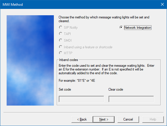
On the MWI Method page, select Network Integration.
Click Next to continue when you are finished.
On the SIP Information page, enter the IP address or DNS name for the PBX in the box provided. Click Next to continue.

On the Voice Ports page, enter the pilot UCD number and the extensions within it.
Click Next to continue.

The final page summarizes your selections so you can review and confirm them. If you need to change something, click Back. You can keep clicking Back until you get to the page you want to edit. Otherwise, click Finish to save the configuration and close the wizard.
System Configuration
Run System Configuration to continue configuring the system.
SIP Configuration

An account and password are not required for the ports. If given one for each port then entering them will have no affect. Update: Some installations have used extensions with passwords successfully so either method may work.

Integration
Using System Configuration configure the integration.

Choose NEC MCI under Network Integration. Then click details.

| Setting | Description | Default |
|---|---|---|
| IP or DNS Name | Enter the IP address or DNS name of the PBX. | Blank |
| TCP Port number | Enter the port number used by the PBX for the MCI Link. | 60020 |
| Device number | Enter a device number between 0 and 99. This is configured on the PBX and typically is set to 1. | 0 |
Note: In Version 8 add MCI LAN in servers to auto start